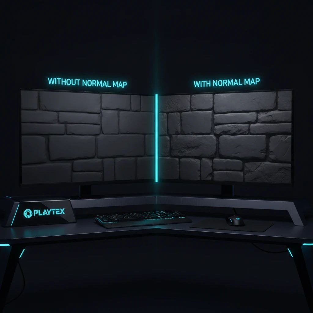
A normal map stores surface directions, not color or literal height.
Tangent-space maps are purple because a flat-facing normal encodes to roughly RGB 128, 128, 255.
An inverted green channel is the usual cause of dents that look like bumps, but UV tangents and color-space settings can also break shading.
Always judge a normal map on the target mesh under moving light, not from the texture thumbnail.
Who Informed This
Written for artists and developers moving material sets between DCC tools and real-time engines, where normal orientation, UV tangents, and import settings commonly disagree.
How It Was Evaluated
Technical claims were checked against the current Khronos glTF specification plus Blender and Unreal Engine documentation. The troubleshooting sequence is designed for a neutral test mesh with a movable light.
Proof And Evidence
The workflow deliberately separates source-image cleanup, normal generation, and engine validation; PLAYTEX can cover the generation step, while the target engine remains the final authority.
Limits And Caveats
A normal map cannot change a mesh silhouette, create true parallax, repair bad UVs, or replace geometry needed for collision and large forms.
Normal maps are one of game art’s best magic tricks. A flat plane catches light as if it had mortar grooves, hammered dents, tiny screws, or reptile scales—yet the triangle count has not moved an inch. The trick lives in that aggressively purple image hiding beside the base color.
This guide explains what the purple pixels mean, where normal maps work beautifully, and why a perfectly reasonable-looking map can turn every rivet into a crater after import.
The 30-second answer
A normal is a direction perpendicular to a surface. The renderer uses that direction when it calculates how strongly a light should affect a point. A normal map supplies a different direction for each texel, so the light reacts as though the surface contains much more geometry than it really does.
The map does not store paint color. It does not store absolute height. It stores a field of tiny directional arrows. Imagine gluing a microscopic compass needle to every pixel, then asking each needle, “Which way should this patch of surface pretend to face?”
The strange colors are packed XYZ directions, not a psychedelic version of the material.
Why is a normal map purple?
Texture files store RGB channels from 0 to 1. A direction needs signed components, typically from -1 to 1. The shader remaps each sampled channel with a calculation equivalent to value * 2 - 1. Red becomes the X direction, green becomes Y, and blue becomes Z.
In tangent space, a completely flat texel points mostly away from the surface: X is 0, Y is 0, and Z is 1. Encoded back into an 8-bit image, that lands near RGB(128, 128, 255)—half red, half green, full blue. In other words: purple.
The glTF 2.0 specification spells out the same remapping and defines its tangent-space convention as +X right, +Y up, and +Z toward the viewer. That is a useful interchange standard, but it does not mean every authoring tool and engine labels the Y direction the same way.
Tangent space, object space, and world space
“Space” answers one question: relative to what coordinate system is the direction stored?
Tangent space stores directions relative to the mesh surface and its UV orientation. It is the familiar purple format and the usual choice for animated characters, reusable props, and tiling materials.
Object space stores directions relative to the object. It can use the full color wheel and may look crisp, but it is less flexible when the mesh deforms or the texture must be reused.
World space stores global directions. Rotate the object and the texture’s idea of “up” does not rotate with it, which makes this a specialized tool rather than a routine asset format.
The Blender Normal Map node documentation describes tangent maps as the common option because they survive object transforms and deformation. It also gives two crucial setup rules: the Image Texture should use Non-Color data, and the normal map must use the same UV map that defines the surface tangents.
The green-channel trap: OpenGL versus DirectX
If a brick’s raised edge suddenly looks engraved, suspect the green channel first. Some pipelines treat green as +Y; others expect -Y. Artists commonly call these OpenGL and DirectX normal-map conventions. Converting between them is wonderfully unglamorous: invert the green channel.
Do not flip it because a forum post says one engine “always” needs a particular format. Importers, project settings, exporters, and plugins can perform that conversion for you. Check the result. Current Unreal import options, for example, include Flip Normal Map Green Channel. If the map already arrived in the correct orientation, flipping it again simply re-breaks it.
What normal maps can—and cannot—fake
Normal mapping changes lighting, not geometry. It excels at shallow features whose illusion is carried by highlights: pores, scratches, fabric weave, stamped patterns, wood grain, chipped paint, or the small bevels baked from a high-poly mesh.
It cannot alter the outer silhouette. Put an enormous “bolt” in a normal map and look at the edge of the model: the bolt vanishes. It cannot cast a physically correct profile shadow, create collision, or provide the deep self-occlusion of a real cavity. Large stones, roof tiles, deep gaps, and gameplay-relevant shapes still need geometry, displacement, parallax techniques, or a carefully chosen combination.
Normal detail is most convincing when its scale is small enough that the missing silhouette is not the star of the show.
Three ways to make a normal map
1. Bake it from geometry
A high-to-low bake transfers surface directions from a detailed sculpt to an efficient game mesh. This is the right route when the map must match specific modeled features. The bake depends on cage setup, UV splits, smoothing, and a tangent basis shared closely enough by baker and renderer. A beautiful high-poly does not rescue a bad cage.
2. Derive it from height
A height image can be converted by measuring how grayscale values change between neighboring pixels. It is fast and effective for mostly planar materials. The result is an interpretation of slopes, however—not recovered truth. A dark knot in wood might be pigment rather than a hole, and a height converter cannot know that from brightness alone.
3. Estimate it from an image or prompt
AI-assisted tools can suggest a normal field from visual structure and are excellent for rapid material exploration. Treat the output as a draft. Baked lighting, painted shadows, and ambiguous shapes can leak into the result. The practical workflow is generate, inspect the channel, correct strength or orientation, then test in the destination renderer.
A 90-second broken-normal checklist
Confirm the texture type. Feed the image through a Normal Map node or engine normal input, not directly into a color or scalar socket.
Disable color correction. Direction data should be sampled as linear/non-color data. Gamma correction bends the vectors.
Check Y orientation. Flip the green channel once. Keep the version whose lighting matches the intended relief.
Check UVs and tangents. Mirrored islands, different triangulation, or a mismatched tangent basis often create seams that no image filter can heal.
Check strength. Crunchy, glittering highlights may be an overpowered map rather than a bad one. Reduce the normal strength before blurring away useful detail.
Check compression and mips. A normal-map compression preset preserves directional data better than ordinary color compression. Inspect the asset from gameplay distance, where mipmaps actually matter.
A sane production recipe
Start with scale. Decide whether one tile represents ten centimeters, one meter, or ten meters. Generate or bake the normal at that physical reading, then preview it beside base color and roughness under a neutral light rig. Rotate the light, tile the material at least 3×3, and inspect both a plane and a curved mesh.
In PLAYTEX, the useful order is source texture first, technical maps second, engine test third. Use the AI Texture Generator when you need a surface concept, or the PBR Map Generator when the source image already exists. Neither button press replaces the last step: the material is finished only when it behaves correctly in the renderer where it will ship.
The tiny-compass rule
When normal maps become confusing, forget the purple image and return to the arrows. Every pixel is merely telling the light which way a microscopic patch should face. If the arrows use the correct space, color treatment, UV tangents, and Y convention, the trick works. If one of those agreements breaks, your heroic rivets become very convincing potholes.